Garrattfan's Modelrailroading Pages
AD60
1.2 Chassis drive units (continued)
| Instructions [22] to [61], page 8-10 of the instruction manual | |
|
|
|
 |
[17] and [23]
These jobs can be done during final assembly, but why procrastinate? Better have the job done and have the parts safely stored in sorting boxes. To my experience the final assembly stage should comprise as few construction jobs as possible. It avoids the "nearly there" syndrome. |
 |
|
The counterweights were glued on the spokes. [23] I used a dab of epoxy glue to glue the counterweights. I avoid CA superglue and will only use it as a last resort. CA is sensitive for thinner and leaves you almost no time to correct. Five minutes before setting is just enough to work one side of both units. Allow to set for two hours, turn the units and do the other sides. In hindsight I better could have trial fitted the counter weight first. Especially the large counter weights on the driving axles have too small a radius on the outside, leaving parts of the spokes uncovered, but the kit has proved to be very accurate so far, so I was taken by surprise. When mounting the wheels on their axles remember that they should be quartered. The right hand wheels should advance over the left hand wheels by 90 degrees when running forward.
|
|
 |
[ 24]
|
[25] De-cusping the main drive rods is again necessary, but you can really tell the difference!! |
|
Identical? NO!! The coupling rods are handed, and the manual does not mention that. Above the left, below the right coupling rod. |
|
Do not remove the cusps from the crank pin holes as they are way too large anyhow |
|
Disturbingly large in fact I'm afraid this will give sloppy performance. The manual optimistically orders you to check for any binding to occur. |
|
 |
[28-29]
|
 |
[30-31] The buffer beam's top side is being cleaned from casting lines by rubbing it over grain 400 emery paper. Other side are scraped and filed. |
One done, one to go When drilling, 2 mm for the buffer and 1 mm for the brake pipes, as per [30], keep in mind that the indicated locations for the buffers are definitely off centre. You'll have to position the drill by your own judgement.
|
|
 |
[32-33] The description on this site may seem detailed but in fact I do not elaborate very much. To demonstrate how many things you must do I have detailed what it takes to complete one set of steps, so you might appreciate why it takes about an hour to makes all four sets
Done!!
|
 |
|
 |
|
 |
[35]
|
 |
To solder the buffers in the buffer beam I put the entire frame upright. The rear was clamped between pieces of wood (paint stirring sticks) to prevent damage by the vise. |
My vise can turn, which makes it easy to work from two sides without having to reclamp the frame again. |
|
The buffer beams after [36]. The brake pipes are loosely fitted for the sake of the photo. I will store them so I can still get to the buffer beam during painting of the chassis. I could attach them after that but as they are in a vulnerable position I won't attach them before final assembly and no sooner. |
|
 |
Oh boy, again a lot of tiny particles. Decusp on all edges, sand smooth on both sides. 12 times if you please. |
 |
[38] Cutting the hand grips to size was made easy by a little tool. I cut a piece of rod to 7 mm and soldered it on a scrap piece of brass. I used it to position the flush cutter exactly to 7mm and then cut off the hand grip. Measure once, cut four! Note that the pilot front plate between the frames already has been fitted as per [41] |
 |
Snip!! O yes, and sand the top flat |
 |
[38-40] Lamp iron, hand grips and buckeye lifting brackets in place. The order and size of the holes to be drilled is: 0.7 - 0.5 - 0.6 - 0.5 - 0.5 - 0.6 - .0.5 - 0.7
Note that the buckeye lifting brackets are positioned under an angle of 45 degrees. As to placing solder: apply the good practise of cutting a tiny piece of solder and place it onto joint and in the flux before working it with the iron. DO NOT pickup solder with your soldering iron and than solder. The quantity of solder you pick up will be uncontrollable and usually way too much. This invariably means a lot of rework for removal of the excess solder. The "cut and place beforehand" method is more laborious but you'll get predictable and mostly clean results. Take care not to place too much solder. Better do it over than cause the need for rework. You'll be amazed how little solder you actually need!! |
Here you see both bearing washers presented on one unit. |
[44] Fixing the sandbox bearing plate to the frame presented no special problems. Scrape, file and sand excess white metal flush with the frames. [45] I had considerable trouble identifying the bearing washers. The hint is: look for the washers with the threaded holes. |
 |
[46-50] Taking up the assembly of the power clip, I could not find the insulated washer no 200. I made it from 0.75 mm styrene sheet. I put it in my drill and "turned" it to the desired size |
 |
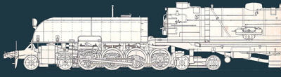
AD60 showing her parts for a model photo shoot ;-) |
 |
Easy. The assembly has not been fitted permanently yet as I have to solder the electric wiring during final assembly after painting.
This setup is required if you make the bogies electrically live as per the instructions of the kit. I decided later to make my own current wipers as I had no confidence in the DJH standard approach. Making my own wipers is described in Making the electric Pickup chapter. If you follow that road, insulating the bogies as describes above is not necessary. Simply do not short out the bogie wheels as per [104] Whatever you do the DJH manual does not take the painting process into account. My advice is to install the wipers, [43], only after painting the chassis. |
[51-61] Now comes another terrible job. Turn up the radio an have a pot of tea at hand and slowly work your way through de-cusping this lot. Over a 100 sides to do!!
The whole brake rigging. It is a bit mysterious that the brake rigging comes with only one brake rod per drive unit which is located definitely off centre. Either there are two off centre brake rods or there is one in dead centre, otherwise the brake rigging will not work well.
|
|
 |
[51-53] If necessary drill the holes to match the 0.7mm wire. A 0.7 mm wire of 25 mm length is passed through the holes in the frame. I made a small tool from scrap brass to push the wire in to exactly the right length, although in hindsight this needn't have been so accurate. |
 |
I soldered the wire with 140C solder to prevent the axle bearings to loosen. The brake shoes were also soldered with 140C solder. This would often cause the solder joint through the nearest frame plate to flow again. This is no problem as the joint through the furthest frame plate will keep the wire in place.
|
Ready for soldering (after [54]) |
|
[56-58] Done. Work carefully. See to it that every single brake shoe is perfectly vertically positioned. Any deviation from vertical will show up as soon as you try to fit the lower four brass rods with the brake actuator rod. You do that all at the same time and then solder all 12 connections on the lower set of rods in one go. |
|
 |
Instruction [59] tells you to cut the protruding wire flush. But I held a piece of 0.3 mm brass in between to retain just a little of the wire so...
|
 |
... after cutting and filing a little bit the wire stands proud just to add a little detail mimicking the hinges of the brake gear.
Also take a good look how clean and straight the brake gear is after all the hard labour of removing the cusps from all sides. Also note that the upper rear wire is left untouched. It will be cut back to 2 mm (somewhat more than advised in instruction 59) to fit the brake tanks. |
The completed brake gear from below |
|
Same from top |
|


Sign my
GuestBook